|
The power steering conversion was going to be the last major fabrication project
that I tackled, so I was anxious to get going on it. There are several different
power steering swaps that are popular for Landcruisers, including Saginaw, Scout,
Mini-Truck, and even using the setup out of an FJ60. For what I wanted to accomplish,
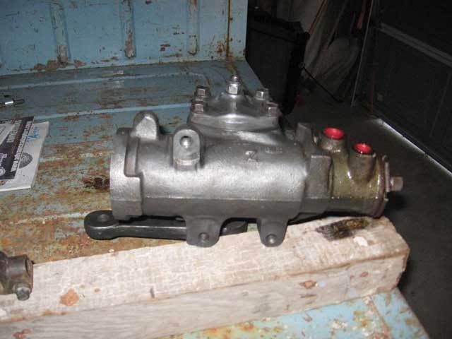
the Saginaw set up was my favorite. But upon further research, I found an even better
solution. Using the steering box out of an Astro Van allowed the steering box to
be mounted *behind* the front crossmember instead of out front near the bumper. This
meant that I would not have to cut a large hole in my front crossmember, and the
steering box would be protected in the engine compartment. So, it was off to the
junkyard to find an Astro steering box.
|  |
|
|
The Astro swap is not very common, so I was only able to find a couple of good technical
write-ups about it. In every instance, the folks doing the swap fabbed up their own
mounting system for the steering box. However, after finding a box in the local junkyard,
I realized that it had the same external casting as the normal Saginaw boxes. The only
difference was that the internal working were changed around so that the pitman arm could
operate in reverse rotation. Based on this discovery, I decided to try and use some
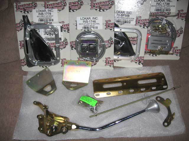
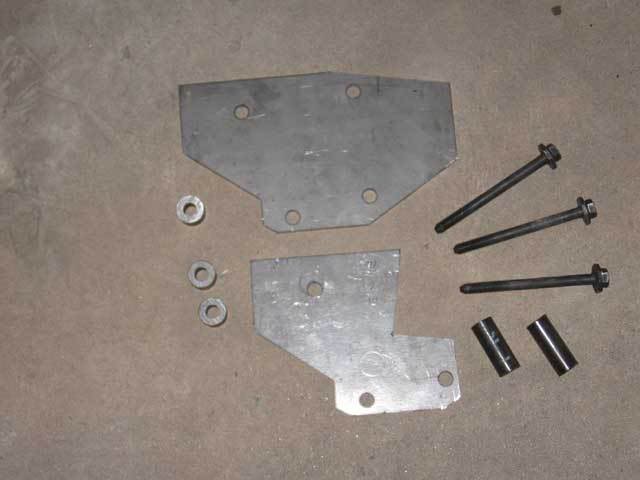
common Saginaw mounting plates usually used in that conversion. For added strength, I decided
to use a second plate on the outside of the frame to spread the load, and some 1/2"
black gas pipe to sleeve the bolts and prevent the frame from squeezing together (three used,
only two shown). The bolts and washers were the grade 8 hardware straight out of the Astro van.
| |
|
|
To get the box to mount where I wanted it, it was necessary to cut the radiused corners
off of the back of the front crossmember to make a 90° corner. I also cut the long
legs off of the bottom of the driver's side radiator mount to clear the box. The frame
begins to angle upward near here, so the box was angled up naturally, which put it at the
correct mounting angle.
| |
|
|
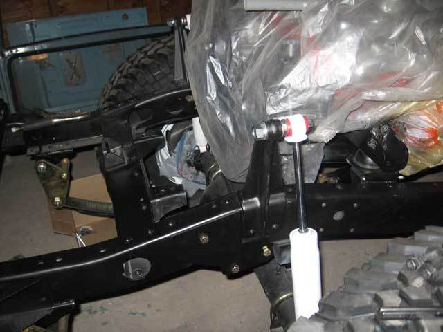
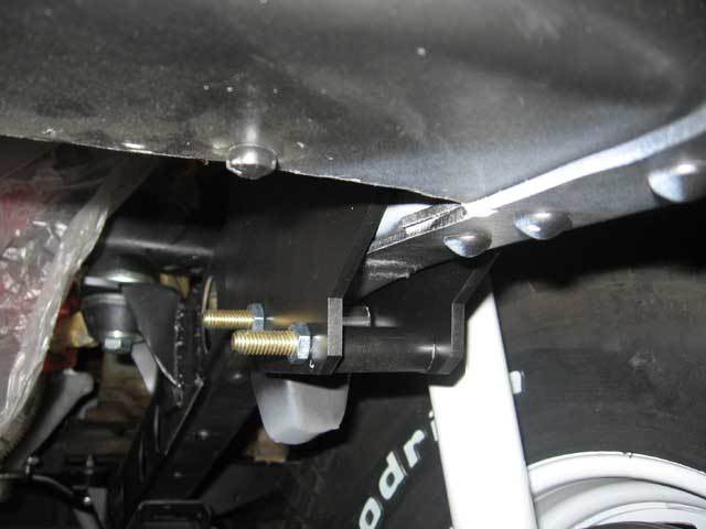
On the outside of the frame, I trimmed the second mounting plate to clear the shock tower
and sit flush against the frame. In this configuration, the top mounting hole goes through
the frame, and the lower two holes are both below the bottom of the frame.
| |
|
|
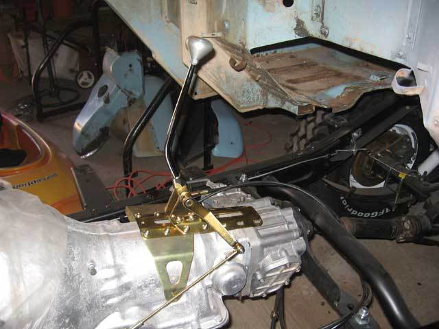
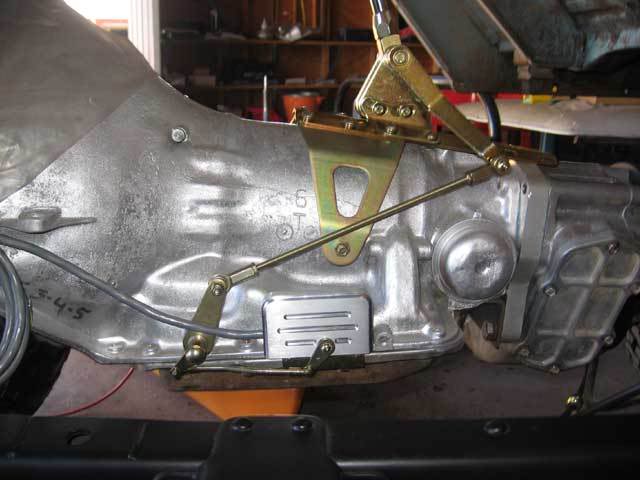
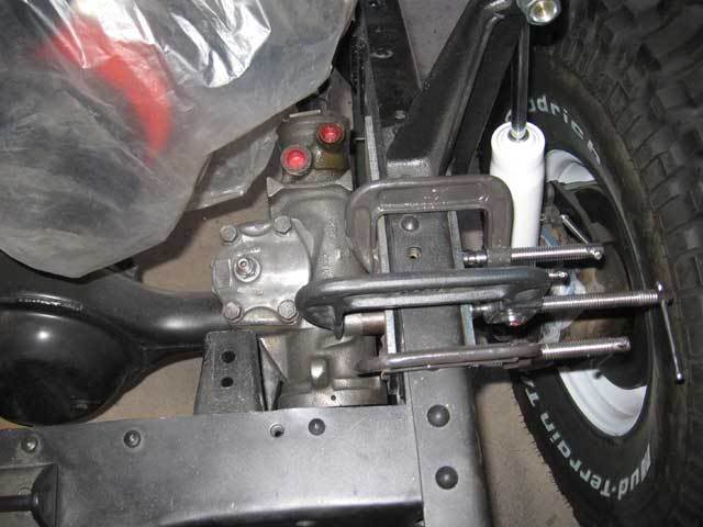
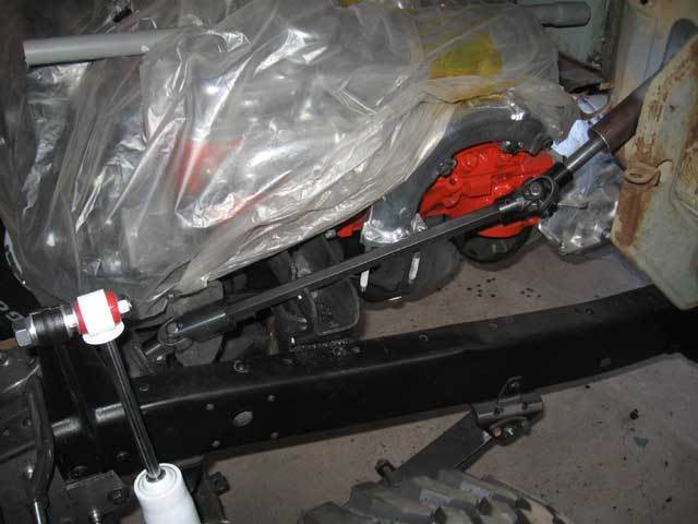
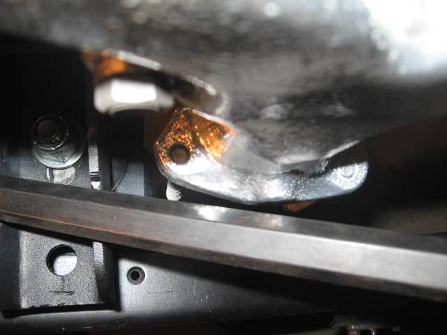
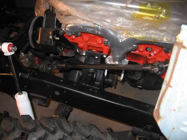
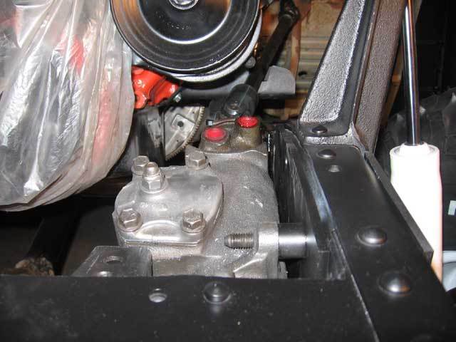
With the box mounted in this position, it sits relatively low in the engine compartment. This
is good in that the box is fully protected by the front crossmember and the flat pitman arm
that I have will probably work good. However, this position makes the steering shaft have a
greater vertical angle to it. It was necessary to notch the motor mount in order to get the
shaft to fit correctly. By mounting the box higher, I could have minimized the notching, but
then the box would possibly start running into the bottom of the power steering pump. (In this
picture, the shaft seems to be rubbing the motor mount, but the shaft is not in its final
position).
| |
|
|
| |
|
|
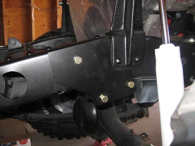
After getting everything lined up how I wanted it, I drilled a hole through the frame for the
top mounting bolt. Some primer and paint for good measure, and i bolted the mounts into place
to make sure everything was still lining up properly.
| |
|
|
| |
|
|
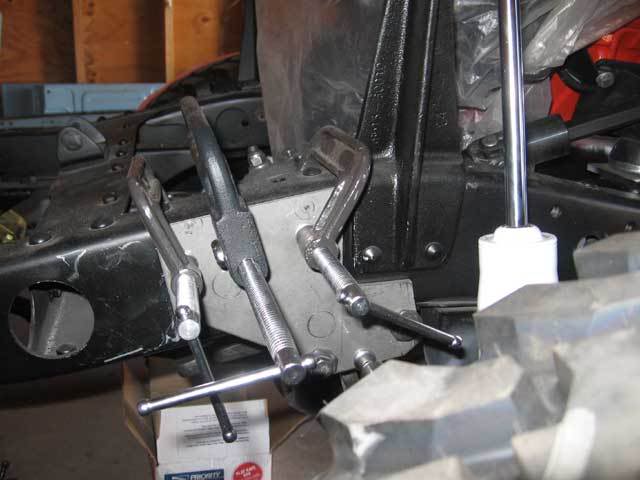
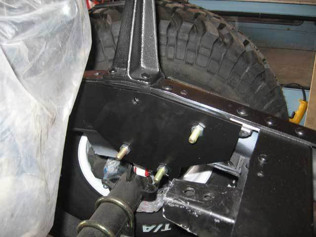
Here you can see the standard mounting plate used on the inside of the frame rail. On the
Astro box, only three mounting bolts are used. I also cut the top-most corner off of the
plate so that it followed the lines of the frame.
| |
|
|
I cut three short pieces of black gas pipe to serve as sleeves for the bolts.
The top sleeve was cut slightly shorter so that it could fit between the inner frame rails.
This should help prevent the frame from collapsing from the torque on the bolts as well
as provide a rigid support for the stress from the box.
| |
|
|
On the other end, I had to deal with the steering column. I cut the column so that it was three
inches shorter than the steering shaft. Normally on the early (pre-72) columns, a bronze
bushing is used to center and support the shaft in the column. Later years can use a pillow
block bearing for this purpose. Although I have the early column, I plan to use a bearing
for the support. The trick here is that the hole in the firewall for early models is very
narrow, so I had to come up with a trick mounting system that would allow the use of the
pillow block *and* allow the column to be removed from the vehicle. More pics of that
set up will follow.
| |
|
|
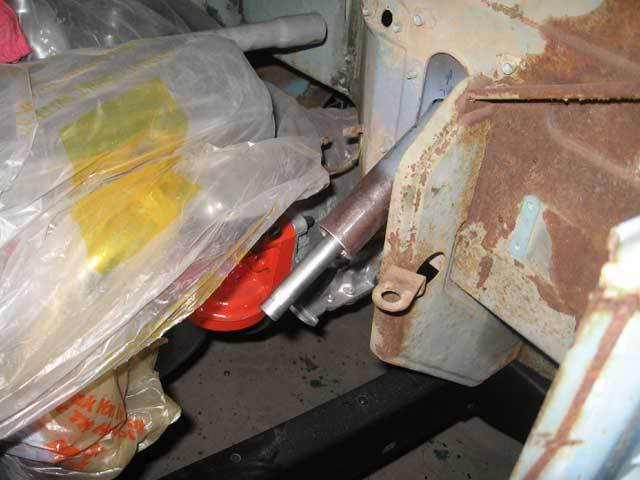
The steering shaft has just enough clearance around the exhaust manifold. This is not the
best picture, but there is at least 3/8" of clearance.
| |
|
|
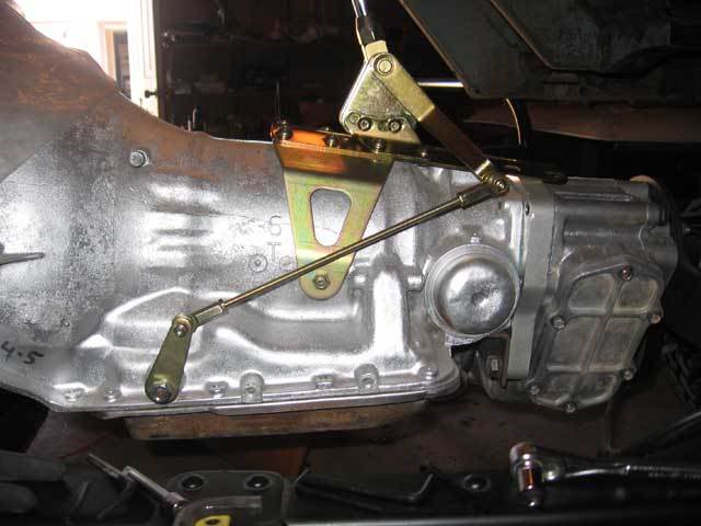
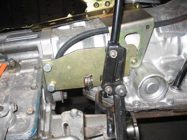
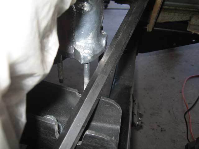
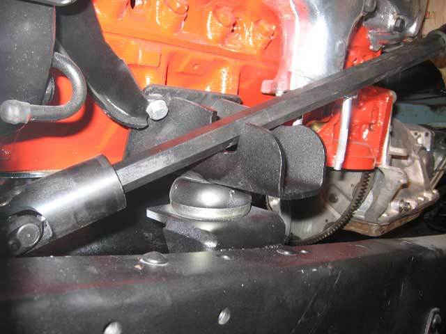
Just showing how much I had to notch the motor mount for proper clearance. The u-joint
at the steering box is a slip joint, so the shaft can move freely inside of it. This
provides a level of saftey in an accident (so that the steering wheel doesnt impale
the driver) and allows for some frame flex in off-road situations that would otherwise
put stress on the steering box input shaft.
| |
|
|
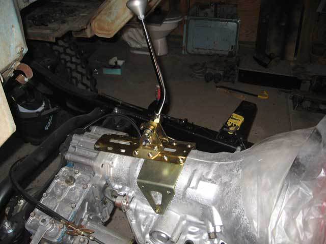
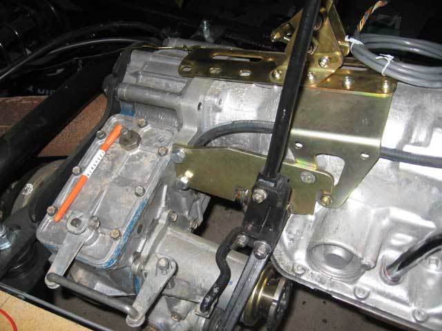
With the box in place, here is the completed set up. Still need to permanently weld the
mounting plates in place and finish up the steering column modifications, but otherwise
this swap is finally done.
| |
|
|
| |
|